
Imagine a critical API service buckling under intense load, causing cascading failures across an entire microservices ecosystem, a scenario that is not uncommon in modern distributed systems where application unavailability due to high CPU usage or memory constraints can disrupt operations. This guide focuses on leveraging Red Hat OpenShift Service Mesh within IBM Cloud Pak for Integration (CP4I) to mitigate these risks through circuit breakers. These mechanisms act as a safeguard, halting requests to unhealthy services and preventing broader system collapse, thereby ensuring operational stability.
Circuit breakers are essential for maintaining resilience in environments with high demand and frequent service interactions. By integrating this pattern using Red Hat Service Mesh on OpenShift, organizations can protect their applications from the domino effect of failures. This guide outlines a structured approach to implementation, covering the setup of the Service Mesh environment, configuration of necessary operators, and testing of circuit breaker functionality to validate system behavior under stress.
The process, while technical, is broken down into manageable steps to accommodate varying levels of expertise. Key actions include installing foundational components, configuring traffic management rules, and simulating failure scenarios to observe protective measures in action. By following this detailed roadmap, readers will gain the ability to fortify their microservices architecture against unexpected disruptions, ensuring consistent performance even during peak loads.
Why Circuit Breakers Matter in Modern Microservices Architecture
In the realm of distributed systems, where numerous services interact constantly, a single point of failure can trigger widespread issues, making protective mechanisms essential. Circuit breakers serve as a critical defense mechanism, designed to detect and isolate problematic services by stopping traffic to them after a predefined threshold of failures. This pattern, deeply embedded in Red Hat OpenShift Service Mesh via Istio, allows for robust traffic management and failure recovery without necessitating changes to the underlying service code.
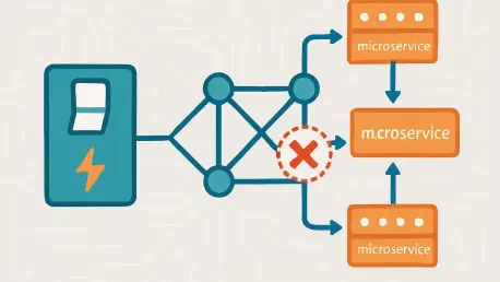
Red Hat Service Mesh operates by deploying sidecar proxies alongside microservices, intercepting and managing all network communications. These proxies, governed by a powerful control plane, enable features like load balancing, service discovery, and security enforcement. The ability to handle failures gracefully through circuit breakers ensures that applications remain responsive, even when individual components falter, making this technology indispensable for maintaining uptime in complex environments.
Tools such as Kiali further enhance the utility of Service Mesh by providing visual insights into mesh topology and real-time monitoring of traffic patterns. This visibility is crucial for understanding how circuit breakers behave under various conditions, allowing administrators to fine-tune configurations for optimal performance. As microservices architectures continue to dominate enterprise solutions, adopting such patterns becomes a cornerstone of building reliable, scalable systems capable of withstanding the pressures of modern workloads.
Step-by-Step Guide to Implementing a Circuit Breaker with Red Hat Service Mesh
This section offers a detailed, actionable tutorial for setting up a circuit breaker to manage an unavailable API service in App Connect on CP4I using Red Hat Service Mesh. Each step is crafted to provide clarity and precision, ensuring that readers with diverse technical backgrounds can follow along and successfully complete the setup. The process encompasses environment setup, service configuration, and rigorous testing to confirm the effectiveness of the implemented solution.
The guide is structured to walk through every necessary action, from installing foundational operators to simulating failure conditions for validation. By adhering to these instructions, the goal is to create a resilient system that automatically isolates failing services, thereby protecting the broader application landscape. Attention to detail in each phase is emphasized to prevent common pitfalls and ensure successful deployment.
Beyond the technical steps, practical tips and insights are included to address potential challenges and optimize outcomes. This comprehensive approach aims to equip readers with both the knowledge and confidence to apply circuit breaker patterns effectively. The following subsections break down the implementation into 22 distinct steps, each building on the previous one to achieve a fully functional setup.
Step 1: Installing Essential Operators for Service Mesh
Begin by logging into the OpenShift console and navigating to OperatorHub. From there, locate and install the Red Hat OpenShift Service Mesh Operator and Kiali Operator within the istio-system namespace. Optionally, consider adding the OpenShift Elasticsearch Operator to facilitate network monitoring and logging capabilities for deeper insights into system performance.
Ensure that the installation process completes without errors by monitoring the status updates in the console, as these operators form the backbone of the Service Mesh environment. They enable advanced traffic management and visualization tools necessary for circuit breaker implementation. Taking the time to verify successful deployment at this stage prevents complications in later configurations.
Key Tip: Verify Namespace Compatibility
Confirm that all operators are installed in the designated istio-system namespace. Using an incorrect namespace can lead to configuration conflicts, disrupting the mesh setup. Double-checking this detail early on saves significant troubleshooting effort down the line.
Step 2: Accessing Red Hat OpenShift Service Mesh Operator
Navigate to the istio-system project within the OpenShift console. From the sidebar, select Installed Operators and click on the Red Hat OpenShift Service Mesh Operator to access its configuration options. This interface serves as the primary hub for managing mesh-related settings and components.
Familiarizing yourself with the layout and available features of this operator is beneficial for efficient navigation during setup. It provides access to critical tabs and tools needed for the subsequent steps, ensuring a smooth workflow. Spend a moment exploring the options to build confidence in handling the interface.
Insight: Operator Accessibility
Understanding the operator’s structure streamlines the management of Service Mesh components. It acts as a central point for initiating and modifying configurations, making it essential to grasp its functionality early in the process, which helps in making quick adjustments and troubleshooting if needed.
Step 3: Creating the Service Mesh Control Plane
Within the Istio Service Mesh Control Plane tab of the operator, locate and click the button to create a basic ServiceMeshControlPlane. This establishes the foundational network infrastructure necessary for managing microservices interactions within the mesh, ensuring seamless communication and coordination. The setup process is straightforward but pivotal for enabling traffic control features.
Once created, the control plane begins orchestrating communication between services, setting the stage for advanced functionalities like circuit breaking. Make sure to verify that the control plane is active and running before proceeding to ensure a stable foundation for further configurations. This step is crucial for the overall integrity of the mesh.
Note: Control Plane Setup
A basic control plane suffices for initial implementations and testing purposes, but for production environments or complex use cases, customization options are available to tailor the control plane to specific needs. Consider these options if scaling or additional features are required later.
Step 4: Configuring Service Member Roll
Prepare a service-member-roll.yaml file with the appropriate code to define the services that will operate within the mesh network. Apply this configuration using the OpenShift command line or console to integrate the specified services into the Service Mesh. This file acts as a registry of mesh participants.
Accuracy in this configuration is vital to ensure that all intended services are correctly recognized by the mesh. Errors in the YAML syntax or service definitions can lead to partial or failed integrations, disrupting traffic management. Review the file contents carefully before applying them to avoid such issues.
Best Practice: File Accuracy
Always double-check the syntax and content of the YAML file prior to deployment. Small mistakes, such as indentation errors or incorrect service names, can cause significant delays, so taking a moment for thorough validation ensures a smoother setup process.
Step 5: Setting Up Kiali for Visualization
From the Installed Operators page, select the Kiali Operator and navigate to the Kiali tab. Click the button to create a Kiali instance, which will provide a graphical interface for visualizing the mesh topology and monitoring traffic behaviors. This tool is invaluable for gaining insights into system dynamics.
Once the Kiali instance is operational, access its dashboard to explore the layout of services and their interactions within the mesh. This visualization helps in identifying potential bottlenecks or misconfigurations early on, and it also provides a clear view of how circuit breakers affect traffic flow during failures.
Advantage: Visual Insights with Kiali
Kiali’s graphical representation of the mesh simplifies the process of diagnosing issues and understanding traffic patterns, making it an invaluable tool for network management. It highlights the status of circuit breakers and other mesh features, making troubleshooting more intuitive. Leveraging this tool enhances overall management efficiency.
Step 6: Accessing the Service Mesh Console
Locate the OpenShift Service Mesh Console tab within the operator interface and click on OSSMConsoles to access the management and monitoring console. This platform provides a comprehensive view of mesh configurations and operational status, serving as a central point for oversight.
Navigating this console allows for real-time updates on service health and traffic rules, which are essential during the setup and testing phases. Keeping this interface readily accessible facilitates quick reference and adjustments as the implementation progresses. Familiarity with its features boosts operational control.
Tip: Console Navigation
Maintain easy access to the console throughout the setup process for immediate reference to configurations and logs. This practice minimizes downtime when addressing issues or verifying settings, ensuring a smoother experience. A well-organized workflow benefits significantly from such accessibility.
Step 7: Building a Sample Message Flow in App Connect
Using the IBM App Connect Toolkit, develop a sample message flow designed to send an HTTP request to a designated back-end URL. This flow simulates typical API interactions, providing a realistic scenario for testing mesh capabilities. Ensure the flow logic aligns with common use cases for accurate results.
This step focuses on creating a controlled environment where the effects of circuit breakers can be observed under defined conditions, ensuring accurate and reliable results. The message flow serves as the client-side component interacting with back-end services, setting the stage for later testing. Precision in its design is key to achieving meaningful outcomes.
Reminder: Flow Relevance
Design the flow to closely mimic real-world API communication patterns. This relevance ensures that test results reflect actual operational challenges, providing valuable insights into system behavior and performance under realistic conditions. Tailoring the flow to specific application needs enhances its effectiveness.
Step 8: Developing a Back-End Application Flow
Create a separate application flow to act as the back-end component supporting the HTTP request simulation in App Connect. This flow handles incoming requests from the sample message flow, completing the interaction loop necessary for testing. Its design should focus on stability and response handling.
Separating the back-end logic from the client-side flow promotes modularity, making it easier to isolate and address issues during testing. This approach also mirrors typical microservices architectures where distinct services handle specific roles. A clear delineation aids in maintaining clarity throughout the process.
Focus: Flow Separation
Emphasize the separation of back-end and front-end flows to enhance modularity and simplify testing. This structure allows for independent updates and troubleshooting, reducing complexity in the development process. Adopting this practice supports scalable and maintainable system designs that can adapt to future needs.
Step 9: Generating the Back-End BAR File
Compile the back-end flow into a BAR file named backend.bar for deployment purposes. This file encapsulates the flow logic in a format suitable for integration servers within CP4I, enabling seamless installation and ensuring that the deployment process runs smoothly. Ensure the compilation process is error-free to avoid deployment issues.
Naming and organizing BAR files systematically prevents confusion during deployment, especially in environments with multiple services. This step is a precursor to making the back-end flow operational within the mesh, so attention to detail in file creation is crucial. Verify the file contents before proceeding.
Caution: File Naming
Adopt consistent naming conventions for BAR files to maintain clarity across deployments. Misnamed or unclear file identifiers can lead to errors in selecting the correct component for installation, so a disciplined approach to naming saves time and reduces mistakes.
Step 10: Deploying Back-End Service to Integration Server
Log into the Cloud Pak for Integration App Connect Dashboard and deploy the backend.bar file to a newly created integration server named backendservice. This deployment makes the backend flow accessible for interactions within the mesh environment, ensuring seamless communication and functionality across connected systems. Monitor the deployment status for confirmation.
Ensuring that the integration server is properly initialized before deployment is essential to prevent runtime errors, as this server acts as the host for back-end operations, facilitating communication with other mesh components. A successful deployment at this stage sets a solid foundation for further steps.
Tip: Server Configuration
Verify that the integration server is fully initialized and configured correctly before deploying the BAR file. Premature deployment can result in failures or incomplete setups, disrupting the workflow. Taking the time to confirm readiness ensures a smoother process.
Step 11: Retrieving Internal Container IP for Back-End
Navigate to Networking > Services in the OpenShift console sidebar to obtain the internal IP address (for example, 172.30.76.254) and port (7800) of the backend-is service. These details are critical for establishing connectivity between services within the mesh, so make sure to record them accurately for reference.
The IP and port information serves as the endpoint for communication, directing requests from other services to the correct destination. Errors in capturing these details can lead to connection failures, so precision is necessary. Cross-check the values in the console to confirm their accuracy.
Key Note: Accurate IP Mapping
Ensure the recorded IP and port match the actual service configuration to avoid issues down the line. Incorrect mappings result in failed communications, derailing testing and implementation efforts. Diligent verification of these details is a small but vital step in maintaining system integrity.
Step 12: Updating Message Flow with Back-End Endpoint
Update the HTTP input flow within the test_circuitbreaker app in App Connect to reference the back-end endpoint using the retrieved IP (172.30.76.254) and port (7800). This adjustment directs requests from the sample flow to the appropriate back-end service for processing. Save the changes after updating.
Accurate endpoint configuration is essential for establishing a functional communication path between services. Mistakes in this step can prevent successful interactions, undermining the testing process. Review the updated flow to ensure the endpoint details are correctly implemented before moving forward.
Precision: Endpoint Accuracy
Pay close attention to endpoint details to avoid connection failures during testing. Even minor discrepancies in IP or port values can disrupt service interactions, leading to errors that could hinder the process. A meticulous approach to this update guarantees reliable communication.
Step 13: Creating BAR File for HTTP Input Flow
Compile the updated HTTP input flow into a BAR file named test_circuitbreaker.bar for deployment. This file packages the client-side flow with the correct endpoint configuration, preparing it for integration within the mesh. Ensure the compilation reflects the latest changes for consistency.
Maintaining alignment between the flow updates and the BAR file content is critical for accurate deployment. Outdated or mismatched files can introduce unexpected behaviors during testing. Verify that the BAR file encapsulates the most recent flow configuration before proceeding to deployment.
Reminder: Consistent Builds
Ensure the BAR file incorporates the latest updates to the flow for accurate representation during deployment. Inconsistencies between the flow design and the compiled file can lead to test failures, so a thorough check of the build process is essential to prevent such discrepancies.
Step 14: Deploying HTTP Service with Sidecar Injection
Log into the Cloud Pak for Integration App Connect Dashboard and deploy test_circuitbreaker.bar to a new integration server named httpservice. Enable sidecar injection by navigating to Advanced Annotations under the deployment settings and setting sidecar.istio.io/inject to true. Complete the deployment by saving the configuration.
Sidecar injection integrates the service into the Service Mesh, allowing for traffic interception and management by the mesh proxies. This step is fundamental to applying circuit breaker policies and other mesh features to the deployed service. Confirm that the annotation is applied correctly to ensure proper mesh integration.
Critical Step: Sidecar Activation
Activating sidecar injection is a non-negotiable requirement for mesh integration, as it ensures that the service is properly incorporated into the system. Without it, the service remains outside the mesh’s control, rendering circuit breakers and other features ineffective. Ensuring this setting is enabled is pivotal for the success of the implementation.
Step 15: Obtaining Admin Console Login Token
Retrieve the OC login token from the OpenShift admin console by selecting the option to copy the login command. This token facilitates command-line operations, providing administrative access to manage configurations and deployments, ensuring efficient and secure management of your OpenShift environment. Store it securely for use in subsequent steps.
Handling the login token with care prevents unauthorized access to the OpenShift environment, ensuring the safety of critical systems. This credential is a gateway to powerful administrative functions, making its protection a top priority. Use secure methods to manage and apply the token during command-line interactions to maintain system security.
Security Tip: Token Handling
Keep the admin console login token secure to avoid potential breaches or unauthorized modifications. Mishandling this credential can compromise the entire mesh setup, leading to significant risks, so adopting strict security practices for token management is essential.
Step 16: Creating Project and Gateway Configuration
Create a new project named service-mesh in OpenShift to organize configurations. Define a Gateway.yaml file to establish entry points for mesh traffic, and apply it using the appropriate command-line instructions. This setup directs external requests into the mesh for processing, ensuring a streamlined flow of traffic within the system for optimal performance and management.
Organizing configurations under a dedicated project enhances manageability, especially in environments with multiple mesh setups. The Gateway configuration acts as the initial point of contact for incoming traffic, routing it to internal services. Verify the application of the YAML file to ensure proper gateway functionality.
Setup Note: Project Organization
Structuring configurations within a specific project like a service mesh simplifies oversight and maintenance, ensuring smoother operations. This organization reduces the likelihood of configuration overlaps or errors in multi-tenant environments, which can often be complex to manage. A clear project framework supports efficient mesh management.
Step 17: Defining Virtual Service for Traffic Routing
Prepare a virtualservice.yaml file to route incoming requests to the httpservice-is container on port 7800. This file creates a wrapper for microservice communication, directing traffic through the mesh to the appropriate endpoint. Apply the configuration to activate the routing rules.
Precise definition of the virtual service ensures that requests reach their intended destination without interruption, and errors in this configuration can misdirect traffic, leading to service failures. Review the YAML content for accuracy in service names and port specifications before application.
Insight: Routing Precision
Accurate virtual service definitions are critical for effective traffic management within the mesh, and incorrect routing configurations can lead to service inaccessibility, disrupting application functionality. Ensuring precision in this step guarantees seamless communication paths.
Step 18: Configuring Destination Rule for Circuit Breaking
Create a destination-rule.yaml file specifying circuit breaker parameters, such as consecutive5xxErrors: 3, to halt traffic after three consecutive failures. This rule enforces isolation of unhealthy services, protecting the system from cascading issues by ensuring that failing services do not impact the overall system performance. Apply the configuration to activate the circuit breaker policy.
Setting appropriate failure thresholds in the destination rule is key to balancing resilience and service availability. Overly strict limits may isolate services prematurely, while lenient settings could allow failures to propagate. Tailor these parameters based on application-specific tolerance levels for optimal protection.
Core Concept: Failure Thresholds
Adjusting retry limits and failure thresholds in the destination rule should reflect the application’s capacity to handle errors. Customizing these settings ensures the circuit breaker activates at the right moment, safeguarding system stability and preventing cascading failures during unexpected issues. Thoughtful calibration of these values enhances overall reliability.
Step 19: Identifying Gateway Route for Testing
In the istio-system project, navigate to Networking > Routes to locate the URL of the istio-ingressgateway route (for example, https://istio-ingressgateway-istio-system.apps.s-ocp.cp.fyre.ibm.com). This route serves as the entry point for testing mesh traffic and service interactions, so be sure to note the URL for use in subsequent tests.
Confirming the accessibility of the gateway route before testing prevents delays caused by connectivity issues, ensuring a smoother process. This URL serves as the external interface to the mesh, channeling requests to internal services. Ensuring its availability is a prerequisite for validating the setup through practical testing.
Testing Tip: Route Verification
Verify that the gateway route is accessible and correctly configured before initiating tests. Inaccessible or misconfigured routes can invalidate test results, leading to false conclusions about system behavior. A quick check of the route’s status ensures readiness for evaluation.
Step 20: Testing HTTP Service Flow
Using an HTTP client, send a request to the identified gateway URL to test the HTTP input flow service. A successful response indicates that the mesh, service integration, and traffic routing are functioning as intended. Monitor the response to confirm proper operation.
This initial test validates the end-to-end connectivity and configuration of the mesh setup. It provides a baseline for normal operation before introducing failure scenarios to assess circuit breaker behavior. Document the results of this test for comparison with subsequent failure simulations.
Validation Step: Response Check
Ensure the response from the HTTP client reflects a successful interaction with the service. A positive outcome confirms that the mesh integration and service deployments are correctly aligned, providing essential validation for the system’s operational integrity.